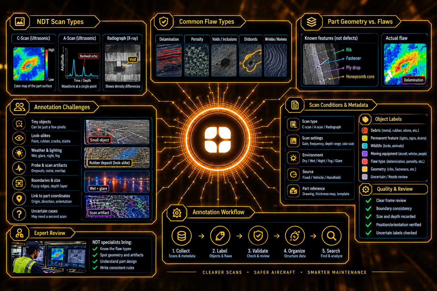
Modern aircraft use composite parts: panels, fairings, and structures built from many thin layers of fiber bonded together. They are strong and light, and they hide their flaws. A part can look perfect on the outside while two layers inside have come apart.
To look inside without cutting the part open, inspectors use non-destructive testing, usually shortened to NDT. They send ultrasound or X-rays through the part and study the result. The scans are large, detailed, and hard to read, so AI is increasingly used to help. Non-destructive testing annotation is the labeling work that teaches it. This post explains what the scans show, what makes them hard to label, and why NDT knowledge matters.
Different tests produce different pictures, and each needs its own labels.
A C-scan is the most common target for labeling.
A C-scan is not a photograph. Its colors represent measurements, such as the strength of an echo or the time it took to return. The same region can look quite different depending on the settings, the color scale, and the depth range being displayed.
Annotators who do not understand this will mislabel what they see. For ultrasonic C-scan labeling, every image should carry its scan settings, and annotators should be trained to read the scale. A patch that looks alarming at one setting may be normal at another.
Composite parts have their own kinds of internal flaws:
A separated layer tends to show as a region with a distinct edge. Porosity tends to show as a diffuse area of altered signal. Telling these apart takes training, and the labels for composite delamination detection data should name the type and not only mark that something is present.
A composite part is not a uniform slab. It has thicker and thinner areas, layers that start and stop, stiffening ribs, fasteners, and honeycomb core with edges inside. All of these produce signals in the scan, and none of them is a flaw.
An annotator without the part's design information will mark them as defects. The fix is to give annotators a reference: a drawing, a thickness map, or a template of known features that can be overlaid on the scan. Anything that matches a known feature is not a flaw, however strong its signal.
Some marks in a scan come from the testing process, not the part. If the probe loses good contact, the scan shows dropouts that look like flaws. Bands may appear where passes overlap. Noise creates speckle, and signals behave oddly near the edges of the part.
Annotators need examples of each artifact so they can recognize it. They also need a way to flag a region as "suspect scan" when the cause cannot be settled, so that someone can rescan the area, not guess.
Where does a flaw start and end? In a scan, the edge of an indication is rarely sharp. It fades through a range of values.
Projects need a written rule for drawing boundaries, such as marking the area where the signal drops by a defined amount from the surrounding level. They also need rules for recording size and, where the scan allows it, the depth layer at which the indication sits. Without a shared method, two annotators outline the same flaw at different sizes, and the model learns an average that fits neither.
A flaw is only useful if someone can find it on the real part. That requires a reliable link between the scan's coordinates and the part's own coordinates.
Scans may start at a corner, run in a particular direction, or be mirrored depending on how the part was set up. If the origin and orientation are not recorded and checked, a label can end up on the wrong side of the part. Every scan should carry its origin and direction, and reviewers should check a sample of labels against the part drawing.
Not every indication can be classified from the scan alone. Some look ambiguous, some sit close to geometry, and some may need a second scan or a different method.
An "uncertain, needs review" label is essential. It keeps annotators from forcing a call, and it points qualified inspectors to the places where their judgment is needed. Acceptance decisions about a part belong to certified personnel using the applicable procedures. The labels support that work and do not replace it.
People trained in NDT read these scans differently. They know how a delamination looks compared with porosity, can spot a probe-contact problem at a glance, and understand how part design shapes the signal. They also know when an indication needs a second look from another method.
They write the rules that keep a large team consistent: the flaw list, the boundary method, the artifact examples, and the handling of uncertain regions. This matches Globik's approach of using verified domain experts for work that depends on judgment. For aerospace NDT AI training data, that expertise is what turns confusing colored maps into reliable labels.
Before an NDT scan labeling project starts, a team can settle five things:
NDT scan AI works when labels respect how scans are made: colors are measurements, part geometry produces signals, and artifacts imitate flaws. For a different example of aviation labeling, see our guide on airfield and runway debris detection imagery: small objects, glare, and wet pavement. Strong non-destructive testing annotation depends on people trained to read what the eye cannot see.
It is the labeling of ultrasonic and X-ray scans so AI can find hidden flaws inside parts.
It is an ultrasonic map of a part seen from above, with color showing how the signal behaved at each point.
Ribs, ply drops, and fasteners produce signals, so annotators need a reference of known features.
A flaw can only be found on the real part if the scan's position maps correctly to it.
They can separate real flaws from geometry and scan artifacts and write consistent rules.